Part 2 ended with the bike's display showing double the real speed above 25 km/h. I hoped that would make the motor stop assisting at 25 km/h, but it did not. In this part I take the chip back to the bike, look at why the motor kept running, find a second wire that does stop it, and then strip the design right back.
The short version: the chip now listens to the speed wire and pulls the brake line LOW above 25 km/h, which cuts the motor. It took a wrong assumption and a design that I threw away to get there.
The motor kept running
In the field test, the display did what the bench test promised: it climbed with the wheel, and when the real speed went from 24 km/h to 26 km/h it jumped to 52 km/h. However, the motor seemed to continue to supply power even after the speed display doubled.
PROMPT
1Speed displayed on bike display increased from 24km/h to 52km.h as real speed increased from 24km/h to 26km/h. So success. Unforunately the bike's controller continued to provide power to the hub motor
In Part 2 I hoped that a controller with a speed limit above 25 km/h would cut assistance when it saw the doubled speed. This controller did not. Claude Code suggested why. The white wire may only carry the speed to the display. The controller might be working out its own speed from the three commutation hall wires, the green, yellow and blue ones that switch the motor phases, and it might not use the white wire to decide whether to cut power. Doubling the white wire seems to have changed what I could see on the display and nothing else.
The brake lever is a switch
An e-bike controller cuts the motor when the brake lever is pulled. That line is a signal I can reach, and it is much safer than the commutation wires. I measured it with a meter.
PROMPT
1I am working on the Brake-cutoff line approach. I have accessed the brake sensor line red and black wire. 5v and 0.4 mA when I connect meter across the sensor wires
Two numbers tell the whole story:
- About 5 V with nothing connected. The controller holds the line at 5 V.
- About 0.4 mA with the meter connected as a short circuit across the wires. That is the current the line can supply.
5 V divided by 0.4 mA is about 12.5 kΩ, so the controller pulls the line up to 5 V through roughly 12.5 kΩ, and the brake lever connects it to ground. The input is active LOW: 5 V means no brake, and 0 V means brake.
That suits a small chip. The ATtiny85 can join the lever in parallel, and it only ever needs to do one of two things with a spare pin, PB4:
- Pull the line LOW by making PB4 an output set to LOW. The controller sees the brake and cuts the motor.
- Let go by making PB4 an input with no pull-up, which leaves the pin disconnected. The controller's own pull-up raises the line back to 5 V.
PB4 never drives the line HIGH, so it cannot fight the real lever. If the ATtiny fails or loses power, the pin lets go and the real brake lever still works. The 0.4 mA is small enough that no transistor is needed, just a 220 Ω resistor in series.
The first circuit: the chip in the speed path
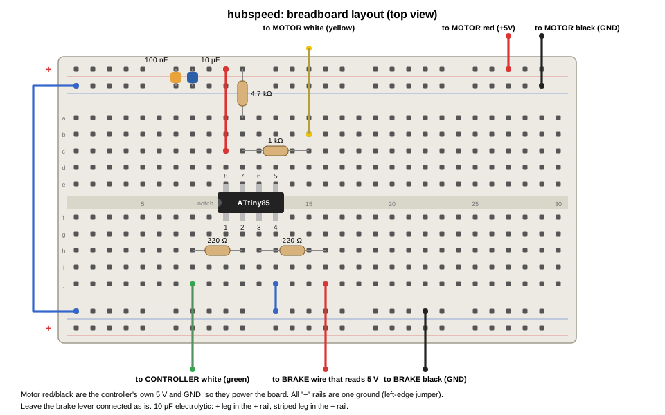
My first brake design kept the chip where Part 2 had put it, between the motor's white speed wire and the controller's. It still mirrored the speed below 25 km/h and doubled it above, and it added the brake line. This is the layout, with the lead for the motor's white wire in yellow and the lead for the controller's white wire in green, the same colours as the wires on the bike.
 Scroll sideways, or tap the diagram to open it full size
The first circuit, seen from above: the yellow lead comes from the motor's white wire and goes through a resistor to the chip, the green lead goes to the controller's white wire from the chip's output, the red and black leads at the top bring power from the hub connector, and the red and black leads at the bottom connect to the brake line
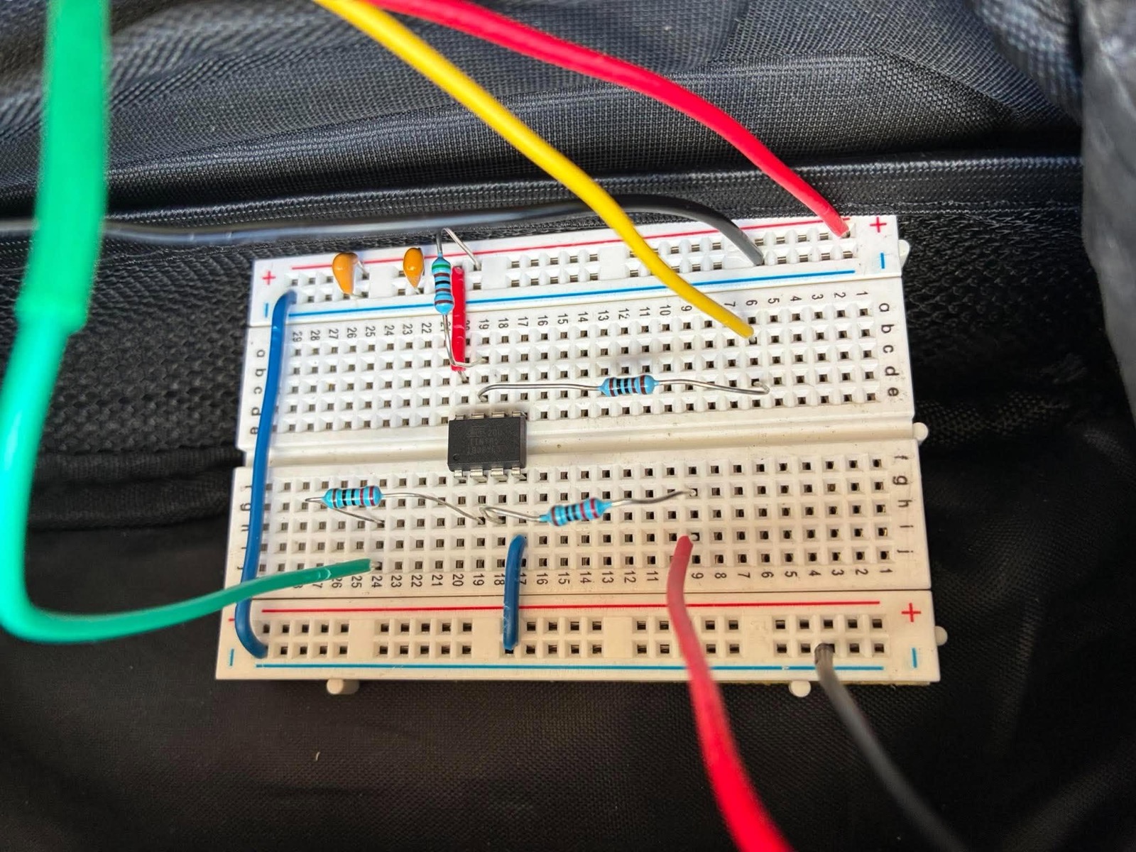
The first circuit on the breadboard in the field test, with the yellow lead coming in at the top and the green lead leaving at the bottom left
The program was the Part 2 sketch with two additions. The chip already measured the real speed from the white wire. Now it also pulled the brake line LOW when that speed was above 25 km/h, and let go below 24 km/h, with the same 1 km/h of hysteresis.
Under the hood: The brake code in the first design
C
1#define BRAKE_PIN    4       // PB4, physical pin 3 (active LOW, open-drain style)
2#define BRAKE_CUT_ON()  (DDRB |=  (1 << BRAKE_PIN))  // output, PORTB bit 0 -> pulls LOW
3#define BRAKE_CUT_OFF() (DDRB &= ~(1 << BRAKE_PIN))  // input, line floats to controller's 5 V
4
5      // Brake-cutoff decision with hysteresis
6      if (!cutting && speed_kmh > SPEED_CUTOFF_KMH) {
7        cutting = true;
8      } else if (cutting && speed_kmh < SPEED_CUTOFF_KMH - SPEED_HYST_KMH) {
9        cutting = false;
10      }
11      if (cutting) BRAKE_CUT_ON(); else BRAKE_CUT_OFF();
The pin is only ever switched between output and input. The output register bit for PB4 stays at 0, so making PB4 an output pulls the line LOW, and making it an input lets it go.
Simplify: join the wires
Once the brake line was doing the work of stopping the motor, the speed path through the chip made no sense. The doubled display was a trick that did nothing useful, and every part of the circuit and the code that existed to mirror and double the signal was a part that could fail. I asked for the simplest design that still works.
PROMPT
1please simplify the hardware and the software so that the yellow and green (signal wire) connect together passing the correct speed from the motor to the controller but still using the brake sensor to cut power to the motor (as if the brake had been pressed) when speed >25km/h refactor hardware and software to be as simple as possible. please update breadboard.svg
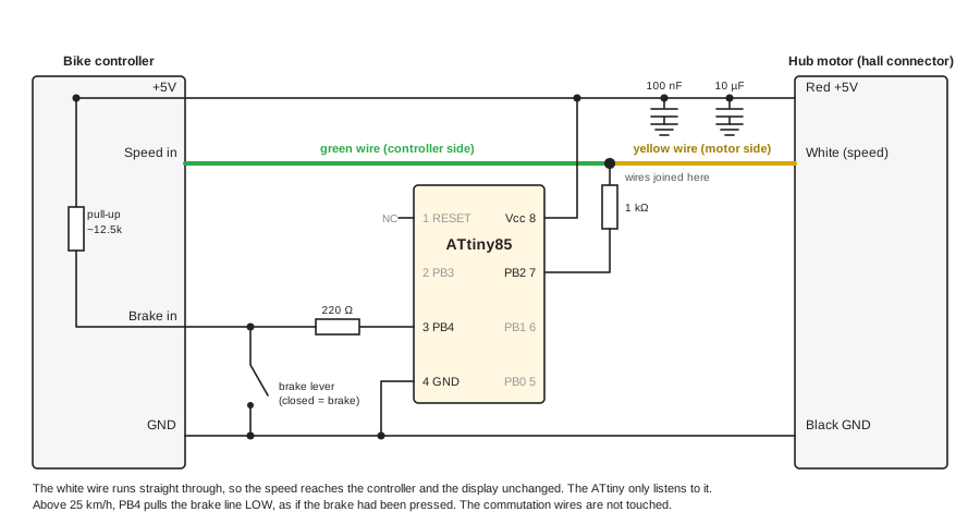
The two halves of the white wire go back together, so the controller and the display get the real speed straight from the motor, exactly as they did before I touched the bike. The chip only listens to that wire and pulls the brake line when the bike is too fast.
 Scroll sideways, or tap the diagram to open it full size
The simplified circuit: the white wire runs straight through, the chip listens to it through a 1 kΩ resistor, and PB4 pulls the brake line LOW through a 220 Ω resistor
This is what went away:
- The 4.7 kΩ pull-up. The controller's own pull-up is back in the circuit now that the wire is whole.
- The 220 Ω output resistor and the whole PB3 output. Nothing comes out of the chip on the speed wire any more.
- The mirroring, the doubling and all the speed arithmetic. The program shrank from 2366 bytes to 580 bytes, about a quarter of the size.
Five parts are left: the ATtiny85, one 1 kΩ resistor, one 220 Ω resistor, and the two capacitors that decouple the supply.
 Scroll sideways, or tap the diagram to open it full size
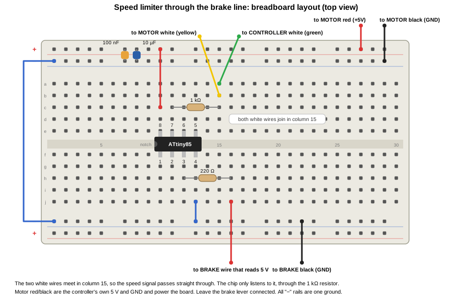
The simplified layout, seen from above: the yellow lead from the motor's white wire and the green lead to the controller's white wire go into the same column, so the column is the join, and a 1 kΩ resistor takes the signal to the chip's input
| Chip pin | Name | Connects to | Through |
|---|---|---|---|
| 2 | PB3 | nothing | |
| 3 | PB4 | the brake wire that reads 5 V | 220 Ω |
| 4 | GND | the hub connector's black wire and the brake wire that reads 0 V | nothing |
| 7 | PB2 | the joined white speed wire, input only | 1 kΩ |
| 8 | Vcc | the hub connector's red wire, +5 V | 100 nF and 10 µF capacitors to GND |
The brake lever itself stays connected. The chip and the lever are two switches on the same line, so either one can apply the brake. If the chip fails, the speed wire is still joined and the brake line floats free, so the bike behaves as it did before.
The program is now short enough to read in one go. Instead of working out the speed in km/h, it compares the time between wheel pulses with two fixed limits. A 29 inch wheel is 2.314 m round, and the wheel has 6 magnets, so 25 km/h is a pulse every 55 538 µs and 24 km/h is a pulse every 57 852 µs. A shorter gap means a faster bike.
C
1#include <avr/interrupt.h>
2
3#define HALL_IN_PIN  2       // PB2, physical pin 7
4#define BRAKE_PIN    4       // PB4, physical pin 3
5
6// Output register bit stays 0, so switching the pin to an output pulls
7// the brake line LOW, and switching it to an input lets it go.
8#define BRAKE_ON()   (DDRB |=  (1 << BRAKE_PIN))
9#define BRAKE_OFF()  (DDRB &= ~(1 << BRAKE_PIN))
10
11// Time between wheel pulses at a given speed
12// (29 inch wheel, 2.314 m round, 6 magnets, so 6 pulses per turn):
13//   25 km/h -> a pulse every 55 538 µs
14//   24 km/h -> a pulse every 57 852 µs
15const uint32_t CUT_PERIOD_US     = 55538UL;   // shorter than this: faster than 25 km/h
16const uint32_t RELEASE_PERIOD_US = 57852UL;   // longer than this: slower than 24 km/h
17const uint32_t MIN_PERIOD_US     = 10000UL;   // shorter than this is a glitch, not a wheel
18const uint32_t STOPPED_US        = 1000000UL; // no pulse for this long: the wheel has stopped
19
20volatile uint32_t lastFallUs = 0;   // time of the last falling edge
21
22// ------------------------------------------------------------
23//  Pin-change interrupt on the speed wire
24//    each falling edge is one magnet passing the hall sensor
25// ------------------------------------------------------------
26ISR(PCINT0_vect)
27{
28  if (PINB & (1 << HALL_IN_PIN)) return;       // rising edge: ignore
29
30  uint32_t now    = micros();
31  uint32_t period = now - lastFallUs;
32  lastFallUs = now;
33
34  // Ignore glitches, and the first pulse after the wheel was stopped
35  if (period < MIN_PERIOD_US || period > STOPPED_US) return;
36
37  if (period < CUT_PERIOD_US)          BRAKE_ON();
38  else if (period > RELEASE_PERIOD_US) BRAKE_OFF();
39}
40
41void setup()
42{
43  // The controller holds the wire HIGH; the internal pull-up only keeps
44  // the pin quiet if the tap wire ever comes loose.
45  pinMode(HALL_IN_PIN, INPUT_PULLUP);
46
47  PORTB &= ~(1 << BRAKE_PIN);      // latch LOW; only DDRB changes
48  BRAKE_OFF();
49
50  PCMSK |= (1 << HALL_IN_PIN);     // pin-change interrupt on PB2 only
51  GIMSK |= (1 << PCIE);
52  sei();
53}
54
55void loop()
56{
57  // No wheel pulses for a second: the bike has stopped, let go of the brake line
58  noInterrupts();
59  uint32_t last = lastFallUs;
60  interrupts();
61  if ((uint32_t)(micros() - last) > STOPPED_US) BRAKE_OFF();
62}
The interrupt handler does all of the work. Each falling edge on the speed wire is one magnet passing the hall sensor. The handler times the gap since the last edge, ignores a gap that is too short to be a wheel or too long to be a pulse, and then pulls or releases the brake line. The loop only checks that the wheel is still turning. The pin uses the chip's internal pull-up, which only matters if the tap wire ever comes loose, because the controller holds the real wire HIGH. The programmer verified all 580 bytes. The sketch, the circuit and the design notes are in the bikespeed repository.
Power level 3: the brake comes on too early
The simplified version worked at power level 1, where the bike accelerates slowest. At power level 3, where it accelerates fastest, the brake came on at a speed well below 25 km/h and then released. The effect was uncomfortable. I asked Claude Code what was happening.
The chip counts a falling edge on the speed wire as a wheel pulse, and a pulse that arrives too soon after the last one means a fast wheel. At high motor power the wire probably picks up electrical noise, so a stray spike looks like an extra pulse, the gap looks short, and the chip decides the bike is fast. The next real pulse then lets the brake go again. Claude Code has not measured the noise. It is the most likely cause, and a meter cannot see it, so the proof needs an oscilloscope on pin 7.
So the program now ignores noise in three ways:
- A real pulse is LOW for several milliseconds. The chip now times the whole pulse, and anything LOW for under 1.5 ms is ignored.
- Pulses closer than 10 ms are ignored.
- One fast pulse is no longer enough. The brake only comes on after 3 fast pulses in a row, and any pulse that is not fast starts the count again.
Claude Code simulated the old and new logic against a simulated wheel signal with noise added. The old logic made between 14 and 229 false brake applications a minute. The new logic made none for narrow spikes and for spikes inside a real pulse, and between 1 and 6 for wide 3 ms spikes. A simulation is not a bike, so the real answer is the next ride.
A 100 nF capacitor from pin 7 to ground is an optional extra. With the 1 kΩ resistor it filters short spikes before they reach the chip, and it costs one part.
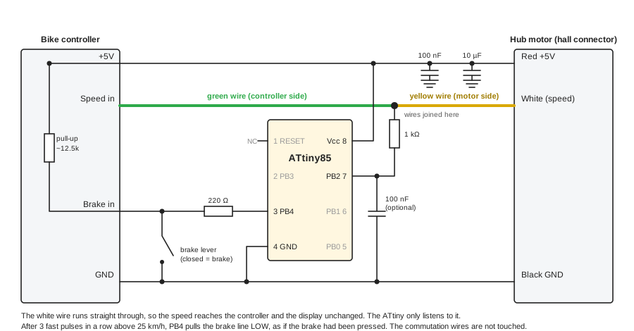 Scroll sideways, or tap the diagram to open it full size
The circuit with the optional 100 nF capacitor on the speed input
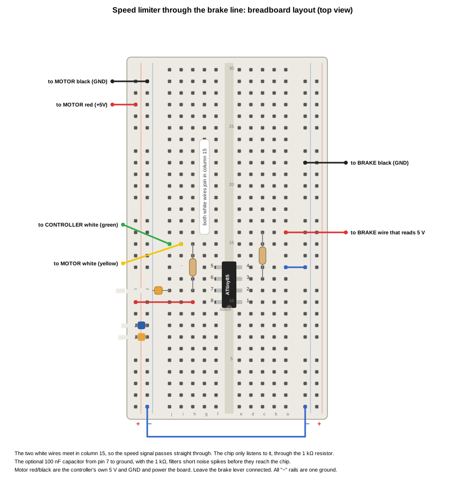 Scroll sideways, or tap the diagram to open it full size
The breadboard with the optional 100 nF capacitor between the pin 7 column and the ground rail, turned to match the way the board sits in the bag
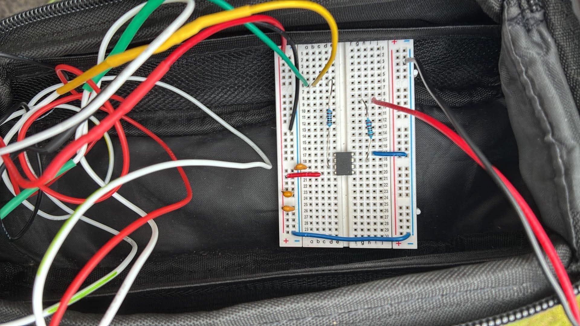
The final breadboard in the frame bag, with the capacitors, the two resistors and the leads to the bike's wires
The new program is 678 bytes. The interrupt handler now runs on both edges of the wire.
Where it stands
To make testing easier, I first lowered the limit from 25 km/h to 10 km/h. Claude Code changed the two constants, rebuilt the program and programmed the chip, and I tried it. It worked: the motor cut out above 10 km/h and came back below 9 km/h. Then I asked for the real limit, and the chip now has the 678-byte program with the noise filter and the 25 km/h limit. The programmer verified all 678 bytes.
After that I rode the bike at power level 3 and filmed the display.
The display climbs through 15, 21, 23 and 25 km/h at power level 3. As it reaches 25 km/h I can hear the hub motor switch off, and the display falls back through 24 km/h
The video shows the cut-out working on the road. As the speed reaches 25 km/h the motor goes quiet, because the chip has pulled the brake line LOW and the controller has stopped assisting. The bike then slows below 24 km/h, the chip lets go of the line, and the motor can run again. Power level 3 is the setting where the brake came on too early before, and this time the motor kept assisting until the speed reached 25 km/h.
Unless I am riding uphill, I always ride in power level 1, so that is the setting that matters most to me. I repeated the road test at level 1, and everything worked perfectly.
What stands out
- A display is not a controller. Part 2 doubled the signal that the display reads, and the display obeyed. The controller never looked at that wire. I should have checked which wire the motor logic uses before I designed around the wrong one.
- Two measurements told me what the brake line is. 5 V open circuit and 0.4 mA short circuit meant a pull-up of about 12.5 kΩ and a line that is active LOW. That was enough to design a safe way to join it, in parallel with the lever.
- Take parts out once they stop earning their place. The doubling circuit and its code only existed to fool the display. Without them the design needs five parts, and there is nothing in the speed path that can fail.