Part 15 ended with an LCD module that Claude Code could talk to, because the board carried its own display and its own library. This time the target is a bare ATtiny85-20PU: an 8-pin microcontroller with no USB port, no LED, and no board around it. The chips came from flashtree, a five-pack listed at $12.99 USD on sale. To write to them I used a cheap USB programmer, the Tiny AVR Programmer, and I asked Claude Code to handle everything else.
Beat 1 — Build the circuit in Tinkercad
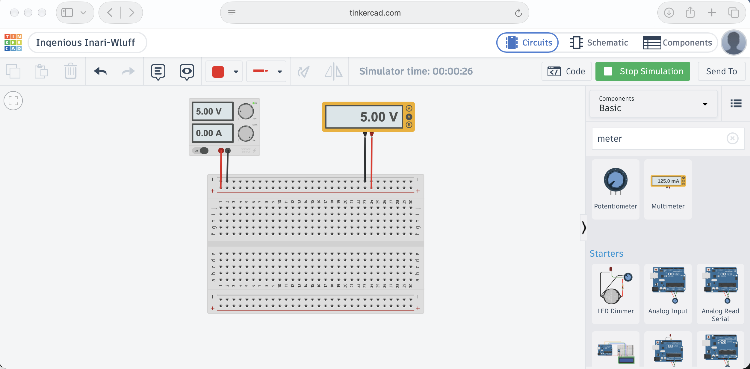
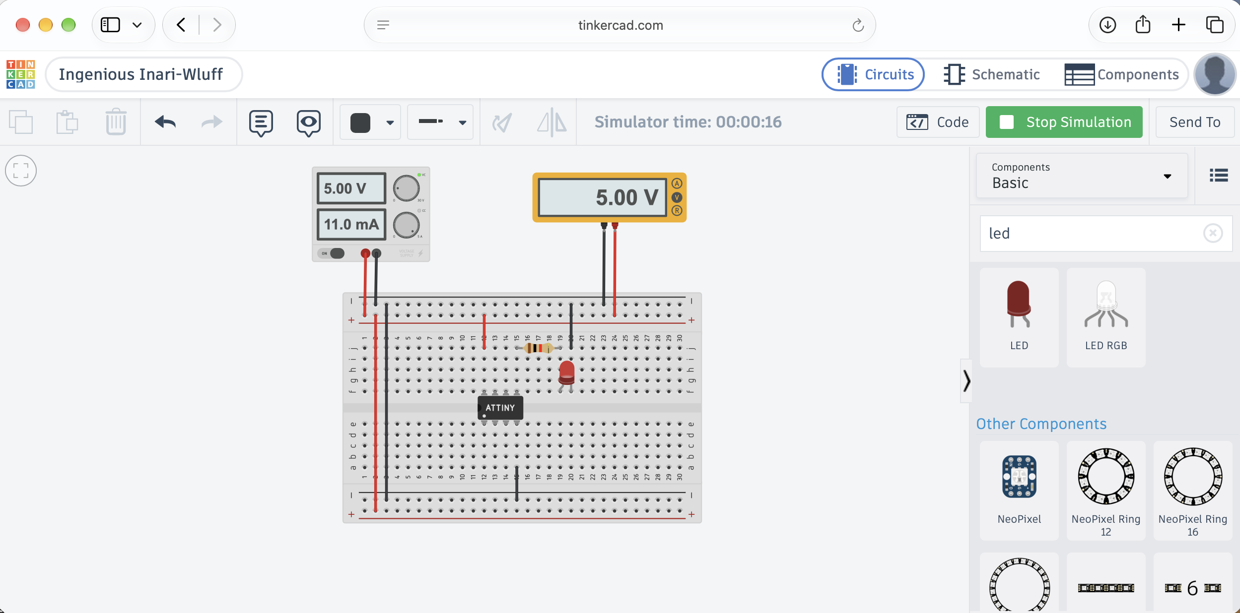
I also built the circuit in Tinkercad, Autodesk's free browser circuit simulator, to check the power and the wiring alongside the real hardware.
 Tap the image to open it full size
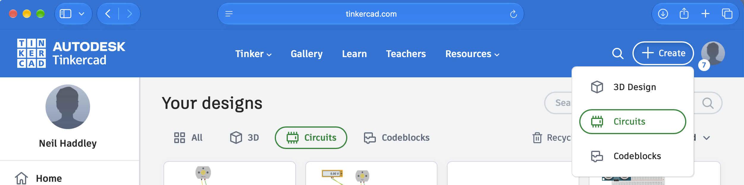
Starting a new Circuits design from the Create menu
 Tap the image to open it full size
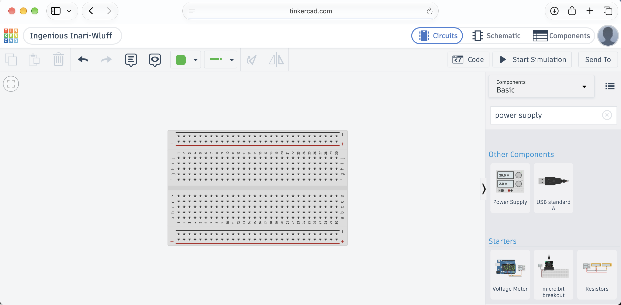
Searching the components for a power supply to drive the breadboard
 Tap the image to open it full size
A running simulation with the supply and multimeter both reading 5.00 V
 Tap the image to open it full size
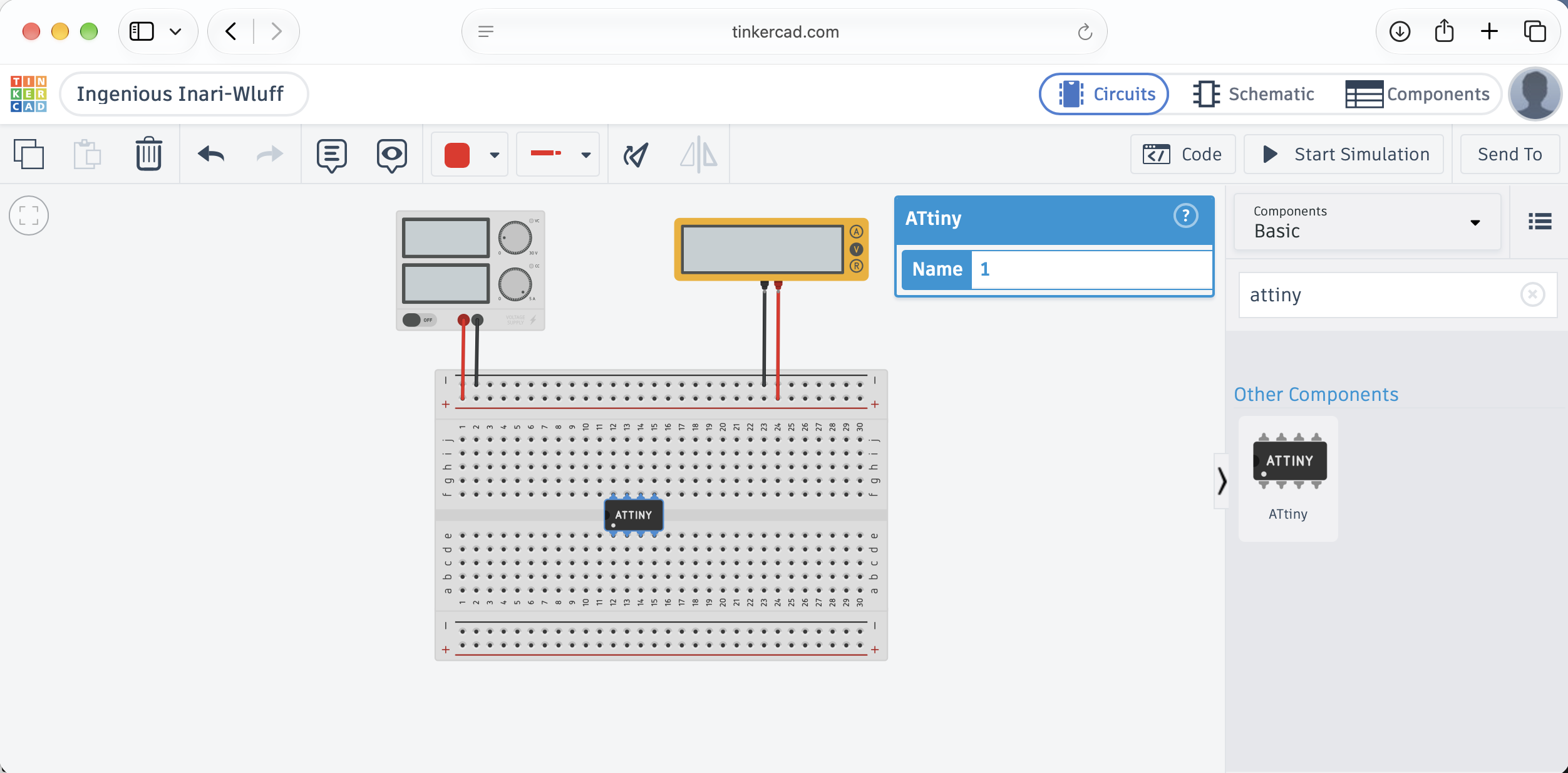
The ATtiny placed on the breadboard and named in its properties panel
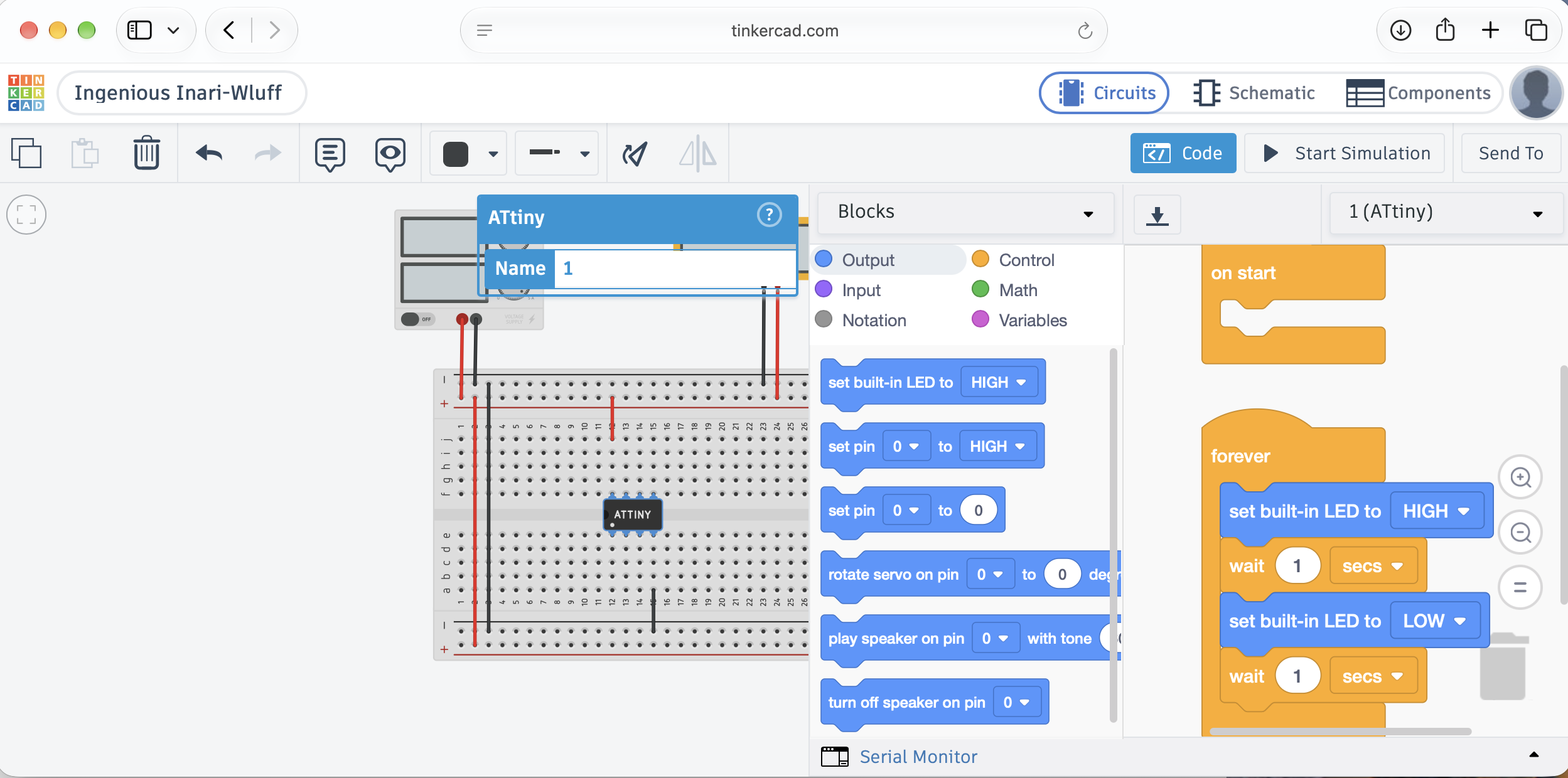
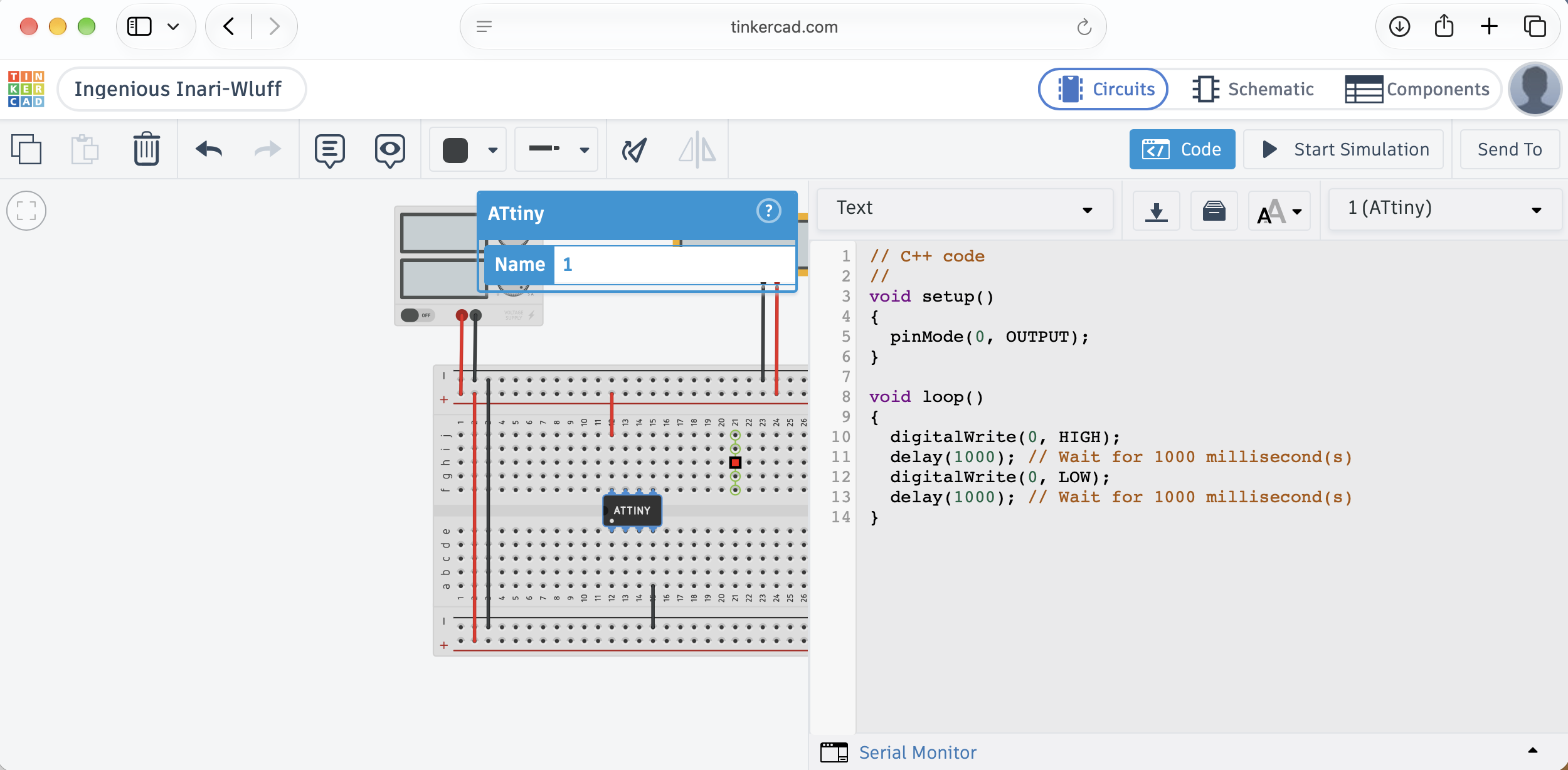
Tinkercad can also program the chip with blocks. I started in the blocks editor, with a forever loop that switches the built-in LED on and off, and then switched to the text view.
 Tap the image to open it full size
The blocks editor, with the LED switched on for one second and off for one second in a forever loop
 Tap the image to open it full size
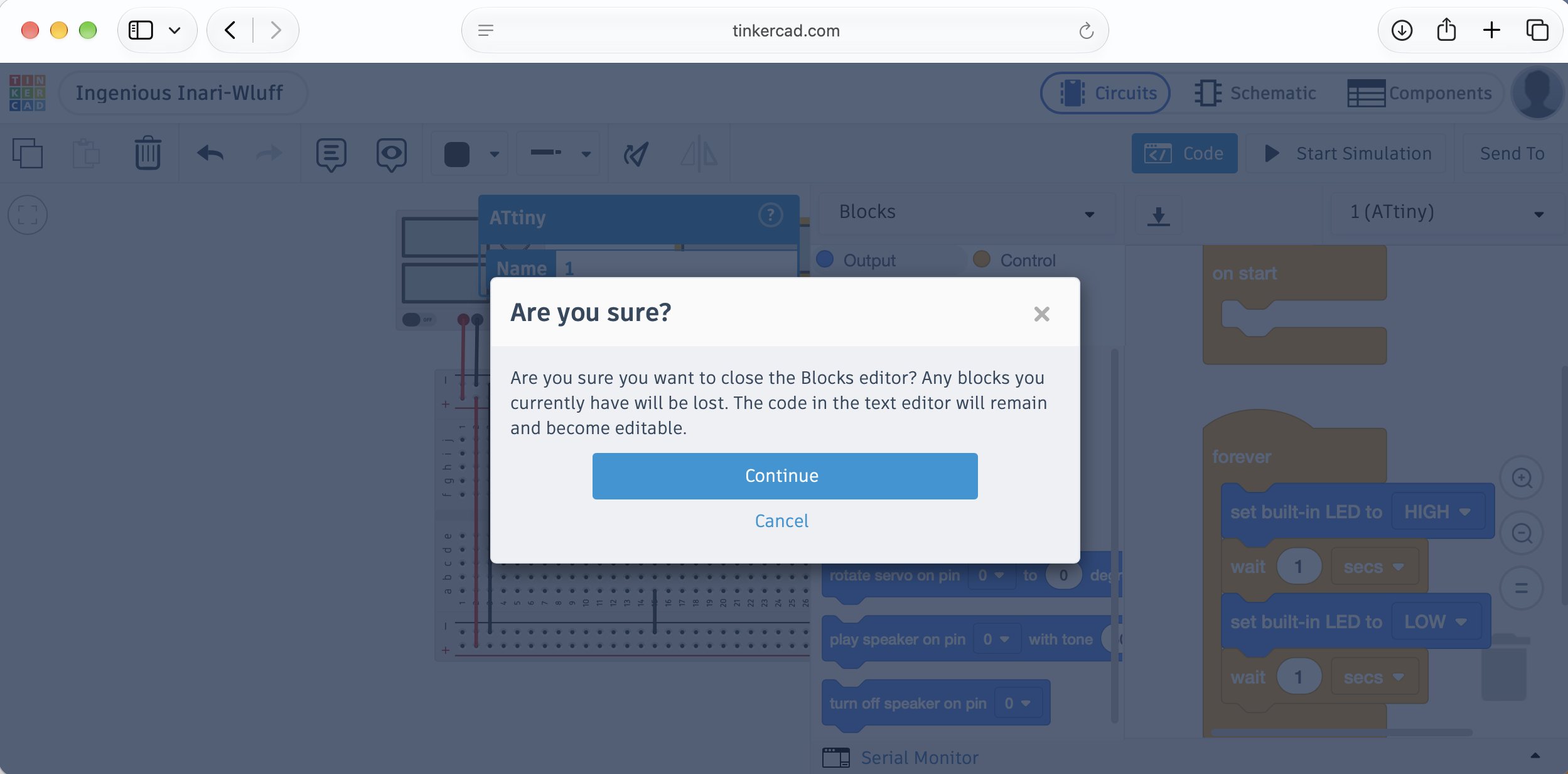
Tinkercad warns that closing the blocks editor loses any blocks you have not converted
 Tap the image to open it full size
The same program as text, with digitalWrite(0, HIGH) and digitalWrite(0, LOW) separated by 1000 ms delays
 Tap the image to open it full size
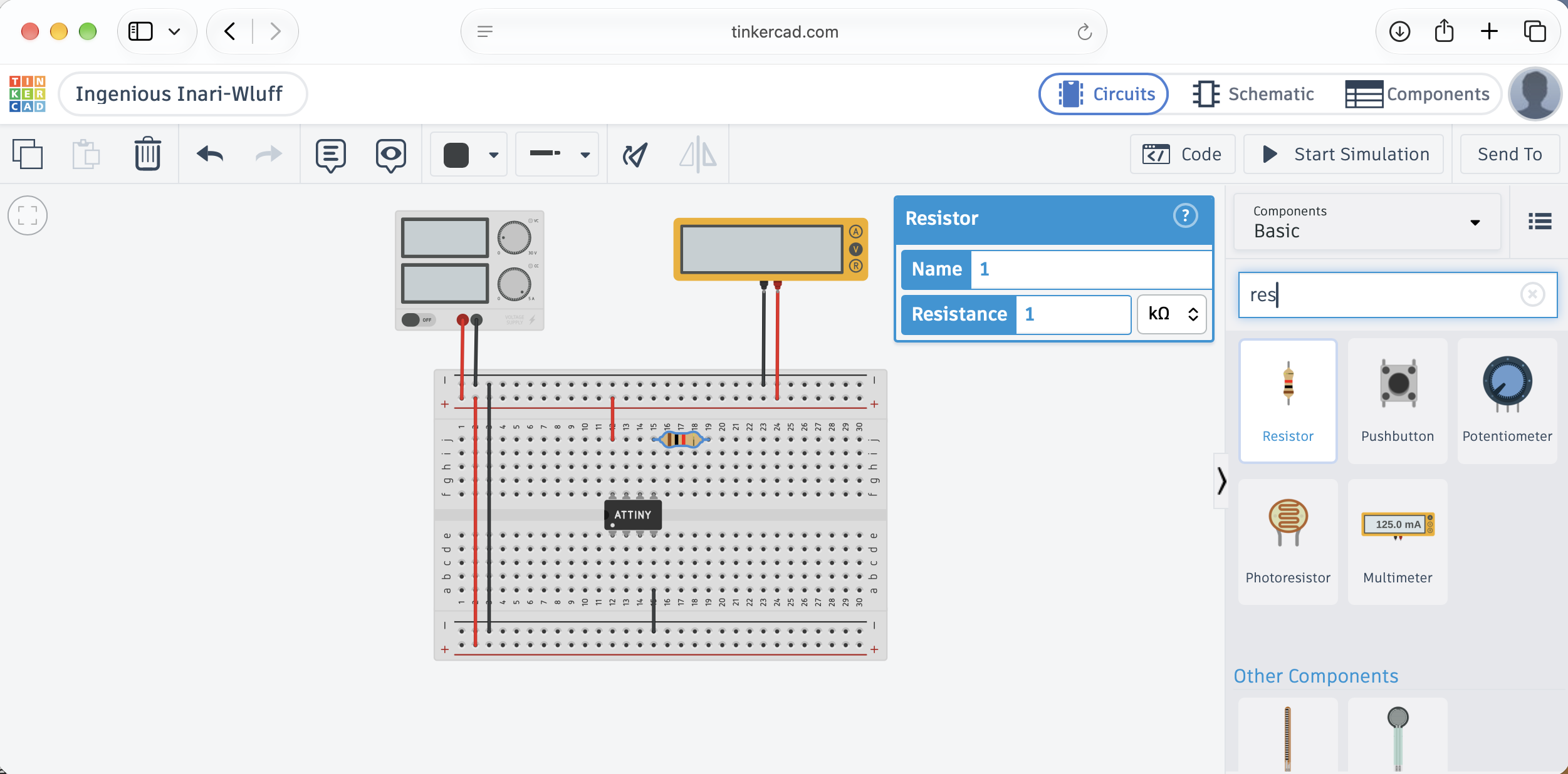
Adding a 1 kΩ resistor to the breadboard
 Tap the image to open it full size
The running simulation with the LED added, the supply at 5.00 V, and 11.0 mA drawn
Beat 2 — Ask Claude Code for a blink program
With the circuit sketched, I asked Claude Code for the real program in a new composer, pointed at an empty project folder.
PROMPT
1create an ATTiny85-20PU blink program and upload to the microprocessor
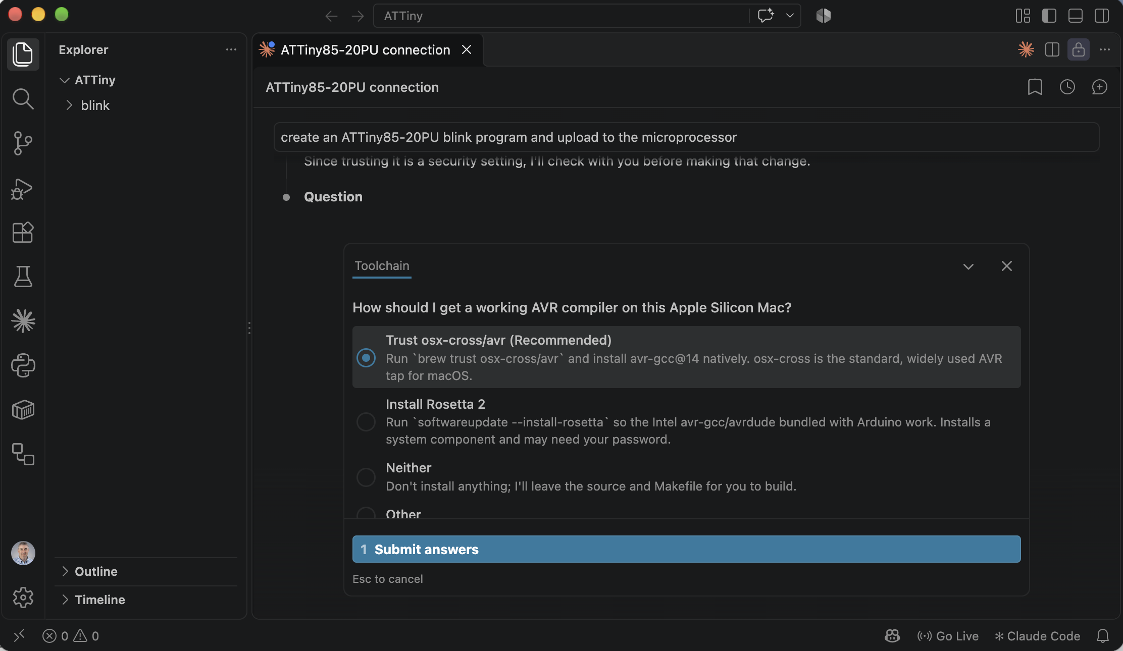
Claude needed an AVR compiler, and on this Apple Silicon Mac there were two obvious ways to get one. It asked me to choose, and it recommended trusting the osx-cross/avr tap. I accepted that recommendation. Claude also said it would check with me before making that change, because trusting a tap is a security setting.
 Tap the image to open it full size
Claude asked how to get a working AVR compiler; I took the recommended option
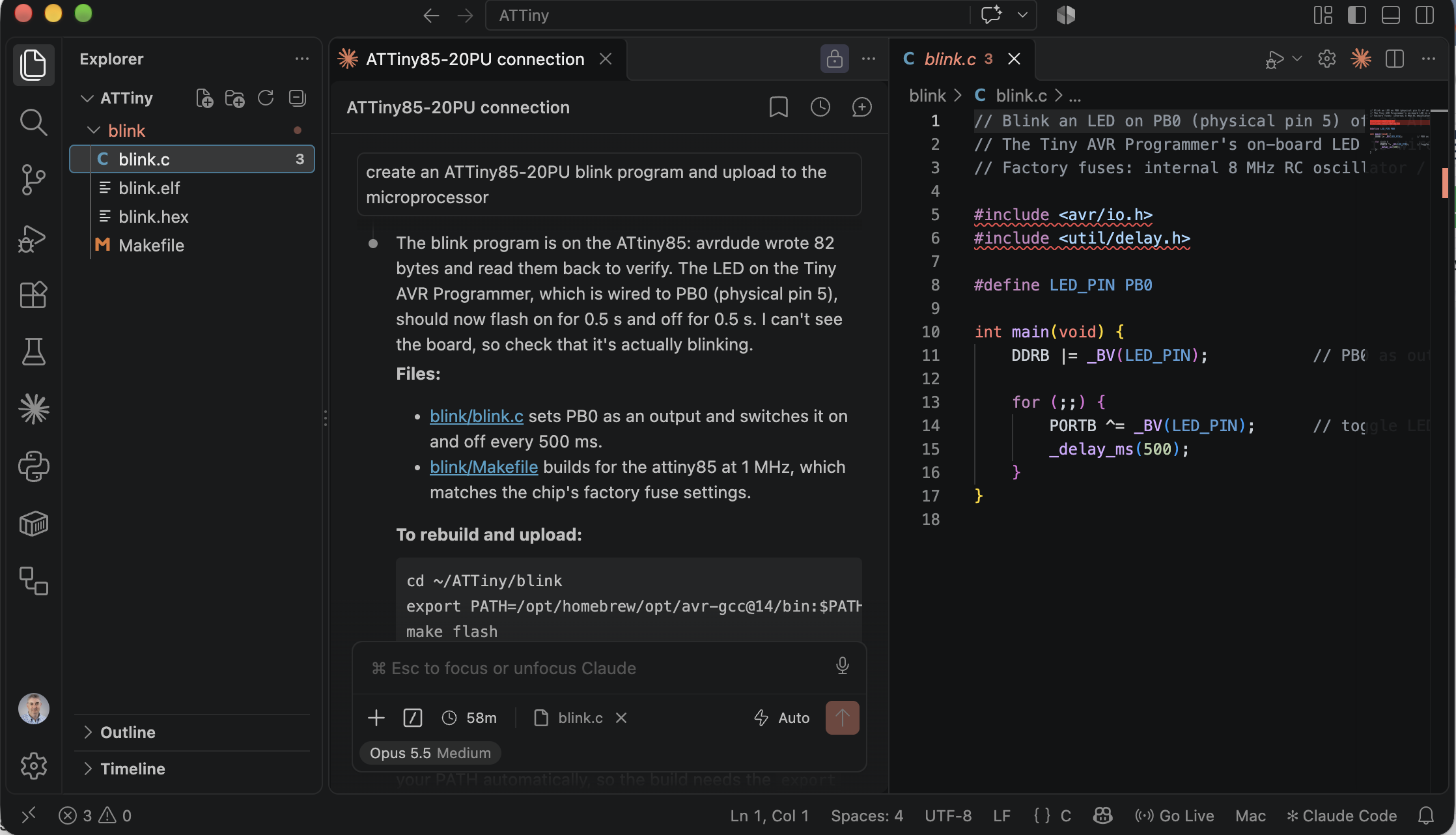
Claude then wrote blink.c and a Makefile and ran the upload. avrdude wrote 82 bytes and read them back to verify them. The build commands it gave me were:
BASH
1cd ~/ATTiny/blink
2export PATH=/opt/homebrew/opt/avr-gcc@14/bin:$PATH
3make flash
 Tap the image to open it full size
Claude wrote the blink program, flashed it, and confirmed the readback; it said it could not see the board, so I needed to check the LED myself
Here is the program, exactly as I pasted it from the project:
C
1// Blink an LED on PB0 (physical pin 5) of an ATtiny85.
2// The Tiny AVR Programmer's on-board LED is wired to PB0.
3// Factory fuses: internal 8 MHz RC oscillator / 8 = 1 MHz.
4
5#include <avr/io.h>
6#include <util/delay.h>
7
8#define LED_PIN PB0
9
10int main(void) {
11    DDRB |= _BV(LED_PIN);           // PB0 as output
12
13    for (;;) {
14        PORTB ^= _BV(LED_PIN);      // toggle LED
15        _delay_ms(500);
16    }
17}
 Scroll sideways, or tap the diagram to open it full size
The blink program line by line, with a note beside each line in my own words
The logic is short. DDRB sets PB0 as an output, and the loop toggles it every 500 ms, so the LED changes state twice a second, a 1 Hz blink. The comment's claim that the programmer's own LED sits on PB0 is the one thing in this program that I could not confirm from the photos. The Tiny AVR Programmer hookup guide says "there's an on-board amber LED connected to pin 0 of the ATtiny85," and adds "The LED is connected to pin 0 in the Arduino environment." Pin 0 in that environment is PB0, which is physical pin 5. So the comment is correct, and the programmer's amber LED is the first thing that should blink.
Beat 3 — Plug in the hardware
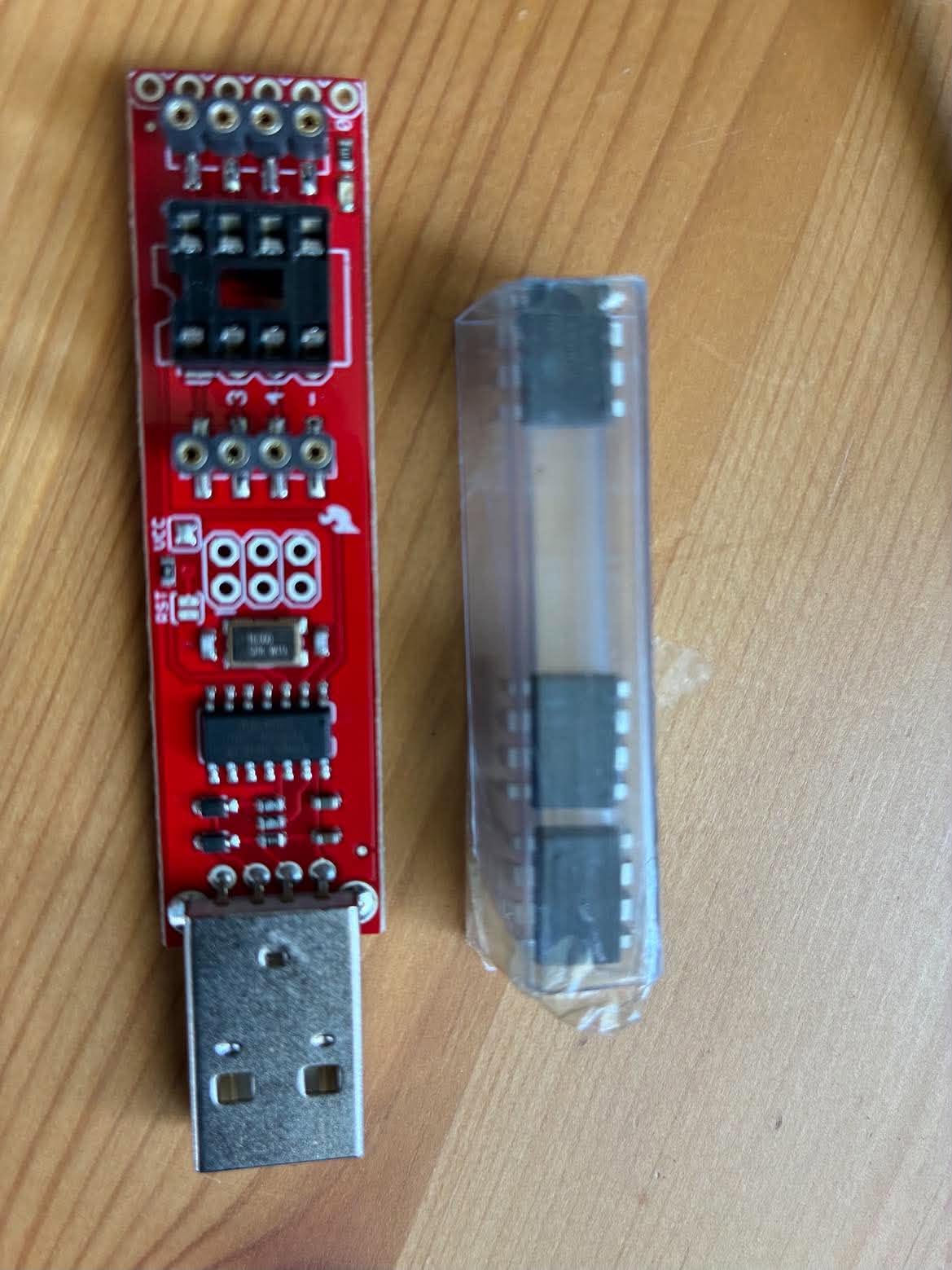
Next came the physical side: the programmer, the chip, and a USB connection.
 Tap the image to open it full size
The Tiny AVR Programmer beside a tube of ATtiny85 chips
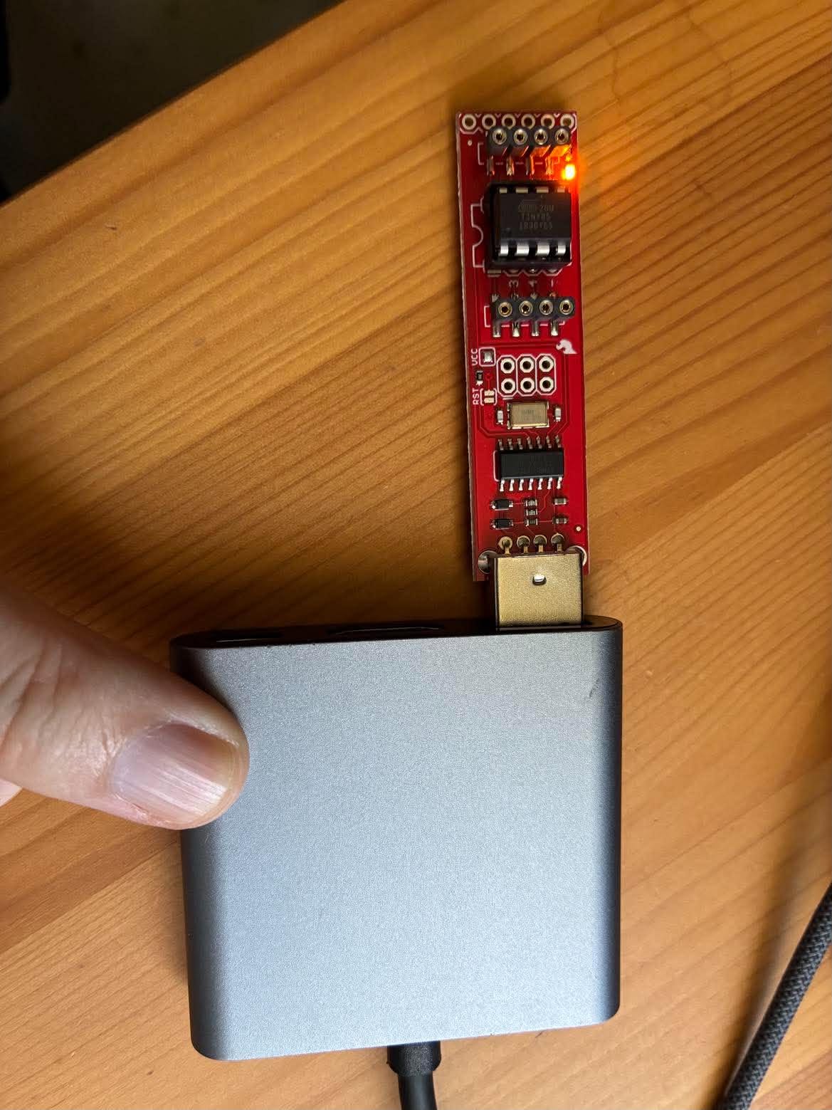 Tap the image to open it full size
The programmer on a USB-C hub with its amber LED lit once it has power
When I plugged the programmer in, macOS asked whether to let the accessory connect. I allowed it.
 Tap the image to open it full size
macOS asks permission before a USB accessory can connect; I allowed FabISP
Beat 4 — Can you see the chip?
I asked the question as a plain sentence, as I did for the LCD module in Part 15.
PROMPT
1can you see ATTiny85-20PU connected via Tiny AVR Programmer
Claude went looking for avrdude first, and found the copy bundled with the Arduino tools. That copy is an Intel binary, and Rosetta is not installed on this Mac, so it would not run. Claude installed a native avrdude with Homebrew and queried the chip in the background.
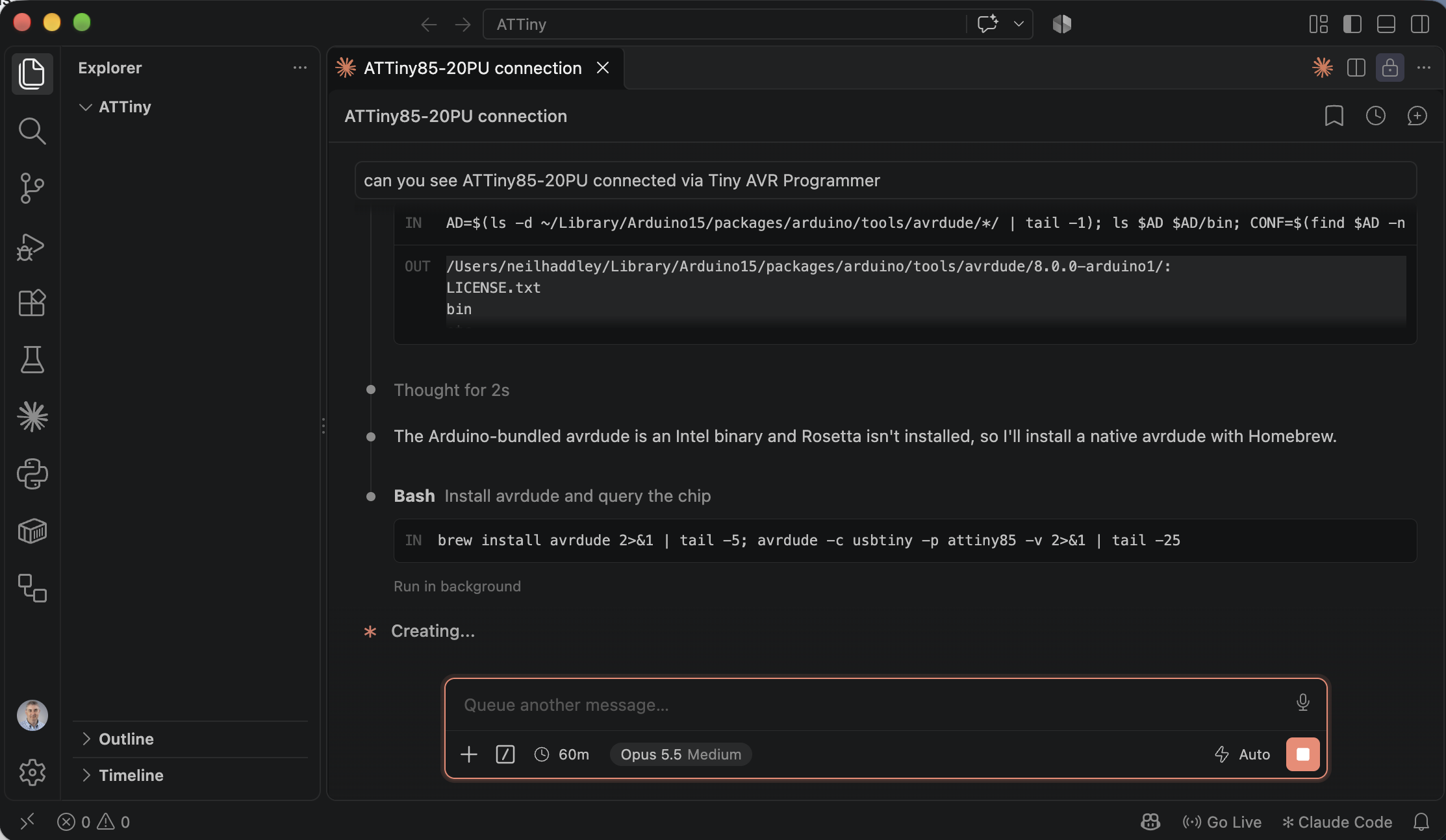 Tap the image to open it full size
Claude found the Arduino-bundled avrdude is Intel-only, then installed a native one with Homebrew
The query worked. Claude identified the programmer and the chip:
- Programmer: a USBtiny, which calls itself "FabISP" (VID
0x1781, PID0x0C9F) - Chip: device signature
1E 93 0B, which is the ATtiny85 - Fuses: low
0x62, high0xDF, extended0xFF, the factory defaults. The chip runs its internal 8 MHz RC clock divided by 8, so 1 MHz. - Upload command:
avrdude -c usbtiny -p attiny85 -U flash:w:yourfile.hex:i - 8 MHz option: set the low fuse to
0xE2if I want the faster clock
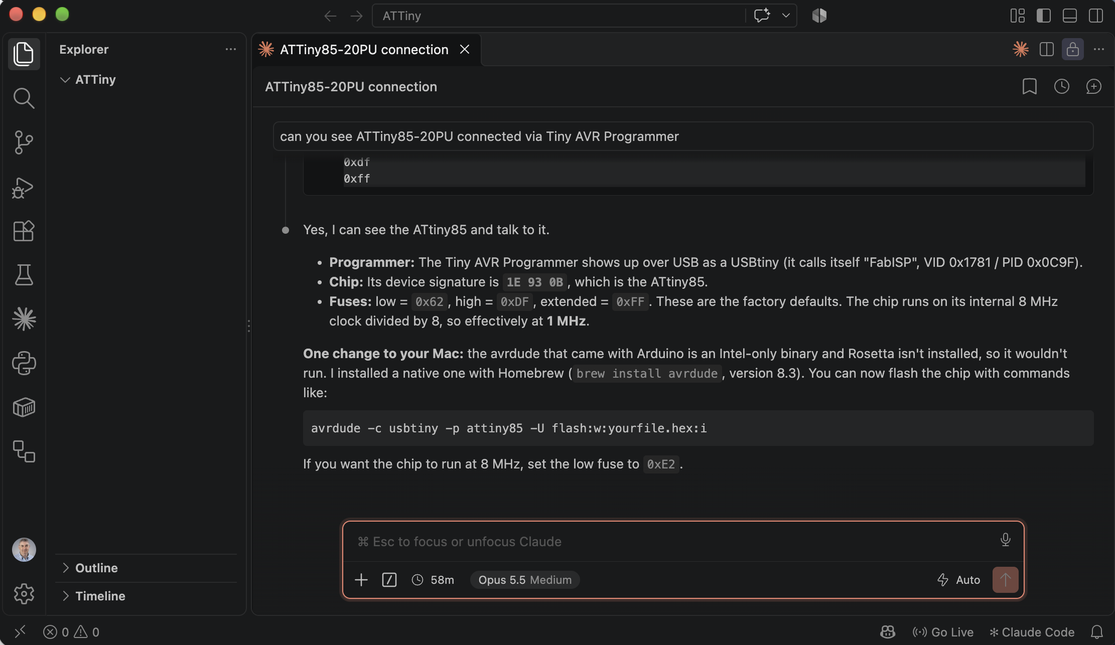 Tap the image to open it full size
Claude identified the programmer, the ATtiny85 signature, and the factory fuse settings
Under the hood: Reading the fuse bytes
The low fuse byte holds the clock settings. Bit 7 is CKDIV8: a 0 there divides the clock by 8. So 0x62 (bit 7 = 0) runs at 1 MHz, and 0xE2 (bit 7 = 1) runs at the full 8 MHz.
Claude also made a point I had not expected: the 1 MHz setting in the Makefile is not an arbitrary choice. It matches the factory fuses, so the delay in the code matches the clock the chip actually runs at, with no change needed on the chip.
The result
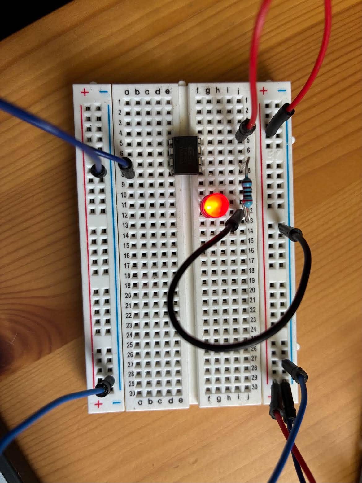 Tap the image to open it full size
The breadboard LED lit on the ATtiny85 circuit. This is a single frame, so it shows that the output works, not the 500 ms timing.
What stands out
- Claude could not see the board, and it said so. Its message after the upload said "I can't see the board, so check that it's actually blinking." The readback from
avrdudeproved the program was written, not that it runs. I checked the LEDs myself. - My own first doubt was wrong. When I read the blink comment against the photos, I suspected that the programmer's LED could not be on PB0. The hookup guide says it is, so the comment was right and my suspicion was not. The lesson I took is to check a hardware claim against a source before publishing it, whether it comes from Claude or from my own reading of a photo.
- The surprises were in the toolchain, not the wiring. Part 15's LCD hid a wiring quirk inside a library's source comments. This chip is bare, so the problems were an Intel-only
avrdudeon an Apple Silicon Mac, and a fuse setting that decides the clock speed the code's delays depend on. - Claude asked before the security change and not before the rest. It stopped to ask before trusting the Homebrew tap. After my answer, it installed the toolchain and a native
avrdudethrough Homebrew without asking again.